WEI Lab Supports the VT FSAE team

2014 Car Rendering

Blacksburg, VA. It took over 25 hours of CAD, CAM, and CNC work to manufacture five different molds that the VF FSAE team will be using to make the panels for its prototype racing car.

2014 Car Rendering

The VT FSAE has been competing for over 26 years and they finished 13th in last year competition. For 2014, the team’s goal is to quality for the International Formula SAE competition in Michigan where 120 other Universities and colleges will compete.

2014 Car Rendering2014 Car RenderingThe VT FSAE is composed of 33 students divided in seven teams including suspension, drivetrain, engine, electrical, aerodynamics, testing, and ergonomics. The final prototype car must be built under FSAE regulations and must past a through inspection before it is allowed to compete.
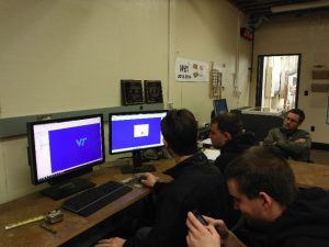
VT FSAE 1For 2014, the team is redirecting efforts to improve several of the car components, including the body. Hence, the team started a search to locate a large CNC equipment that could be used to cut the molds required for the body parts. The material used to cut the molds is a high density foam that is easy to manufacture. The WEI CNC equipment is just what the VT FSAE team needed and under the supervision of Dr. Henry Quesada the team quickly became familiar with the CAD/CAM software and the operation of the  CNC machine.

The way that the VT FSAE operates involves knowledge transfer from senior to freshman students, as key critical factor to be able to compete and complete the project which is very similar to the approach of WEI program at the Department of Sustainable Biomaterials.

VT FSAE 2

The team structure is the following

  •   Team Leader: Vincent Sorrento
  •    Team Moderator: Dan Buckrop
  •     Team Facilitator: Nabeel Ahsan
  • Sub-team structure
  • Suspension
  •         Team Leader: Hannah Bever – Chassis
  •             Nabeel Ahsan, Taylor Turner – Uprights
  •             Alex Pape – Suspension design and geometry, springs, dampers, tires.
  •             Mike Lane – Suspension Structures
  •             Cody Kees – Bell cranks
  •             James Callaway – Steering

Drivetrain

  •          Team Leader: Mackenzie Hoover – Brakes
  •             Alex Coyle – Rear chunk
  •             Alex Girard – Shifting, Simulation
  •             Kyle Torrico, Thomas Barfield – Rotating components
  •             Brian McNulty – Wheel inners, wheel outers
  •             Danny Whitehurst – Half shafts, tripod bearings

Engine

  •          Team Leader: Dan Buckrop – Engine airflow, Intake
  •             Clay Brubaker – Controls, tuning
  •             Johnny Noble, Carter Moore – Oil, Fuel, Cooling
  •             Mark Anton – Engine airflow, exhaust

Electrical

  •          Team Leader: Bryce Crane – Telemetry, diagnostics
  •             Natan Diskin – Wiring
  •             Kori Price, Glenn Feinberg, Brian Kwan – Power stream, power budget module
  •             Tyler Diomedi – Packaging
  •             Daniel Ridenour – Graduate Assistant

Aerodynamics

  •          Team Leader: Stephen Young – Under tray, diffuser
  •             Sean Lynch, Chris van Oss – Wings
  •             James Bizjak – Structures

Testing

  •          Team Leader: Brian Oeters – Test Planning & Data Acquisition
  •             Akira Madono, Dylan Verster – Test Planning & Data Acquisition

Ergonomics

  •          Team Leader: Rachel White – Project management, cost analysis
  •             Eric Peterka, Jeff Petrillo – Pedal box
  •             Matt Marchese, Lucas Keese – Steering wheel, seats
  •             Sam Ellis – Cost analysis, facilities planning.

If you have any more questions about student CAD/CAM/CNC projects that the Department of Sustainable Biomaterials support, please contact Dr. Henry Quesada at quesada@vt.edu.

 

RESEARCH BRIEF: Lean Product Development

by Sevtap Erdogan, email  serdogan@vt.edu

The implementation of Lean Product Development is based on applying lean principles to be able to gain more economic benefits. The goal is to focus on decreasing process variability, maintaining flow and reducing waste (Achieving Lean 2004).

Lean Product Development has been incorporated into organizations with the motivation of maintaining higher value and quality, shorten lead times, and lower costs This last one motivator was was not successful enough when conducting or implementing traditional product development process (Leon et al, 2011).

SIM article 1 pic
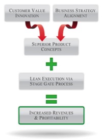
Lean Product Development (Anonymous 2004)

Ward (2007) states that to provide better understanding in implementing lean product processes, manufacturers need to seek for the importance and the purpose of product development, product itself, good development system and value in product development.

Commonly, Lean is mostly found proper for manufacturing process related with material supply, component production, and delivery of products. Nevertheless, besides manufacturing operations lean thinking can also be applied to Lean Product Development (LPD) (Morgan and Liker, 2006). The difference between LPD and traditional product development is specifically the underlying of the numerous benefits by using the LPD’s own flow over the whole process (Karlsson and Ahlstrom, 1996). Supplier involvement is one technique used in the LPD that targets the incorporation of suppliers at the beginning of the process other than in some parts of the project. Simultaneous engineering (or concurrent engineering) term is used in this process and it can be defined in a simple was as driving in parallel different activities (Karlsson and Ahlstrom, 1996).

Most of companies have adjusted state-gate process in order to deliver value to all stakeholders by decreasing waste and smoothing the value stream in product development processes. There are two notable benefits with regard to this concept, (a)better design activities improvement with the adjustment of tools in lean and (b) integration with lean among marketing research, conceptual design, product design, test and verification, and ramp-up product (Wang et al, 2011).

References

  • Anonymous. 2004. Achieving lean product development. Strategic Direction, 20(7/8), 33.
  • Karlsson, C., & Åhlström, P. (1996). The difficult path to lean product development. Journal of Product Innovation Management13(4), 283-295.
  • León, H.,C.Mart, & Farris, J. A. (2011). Lean product development research current state and future directions. Engineering Management Journal, 23(1), 29-51
  • Morgan, J. M., & Liker, J. K. (2006). The Toyota product development system. New York: Productivity press.
  • Wang, L., Ming, X. G., Kong, F. B., Li, D., & Wang, P. P. (2011). Focus on implementation: a framework for lean product development. Journal of Manufacturing Technology Management23(1), 4-24.
  • Ward, A. C. (2007). Lean product and process development. Lean Enterprise Institute.

Third Innovation-based Manufacturing Workshop: A great success!

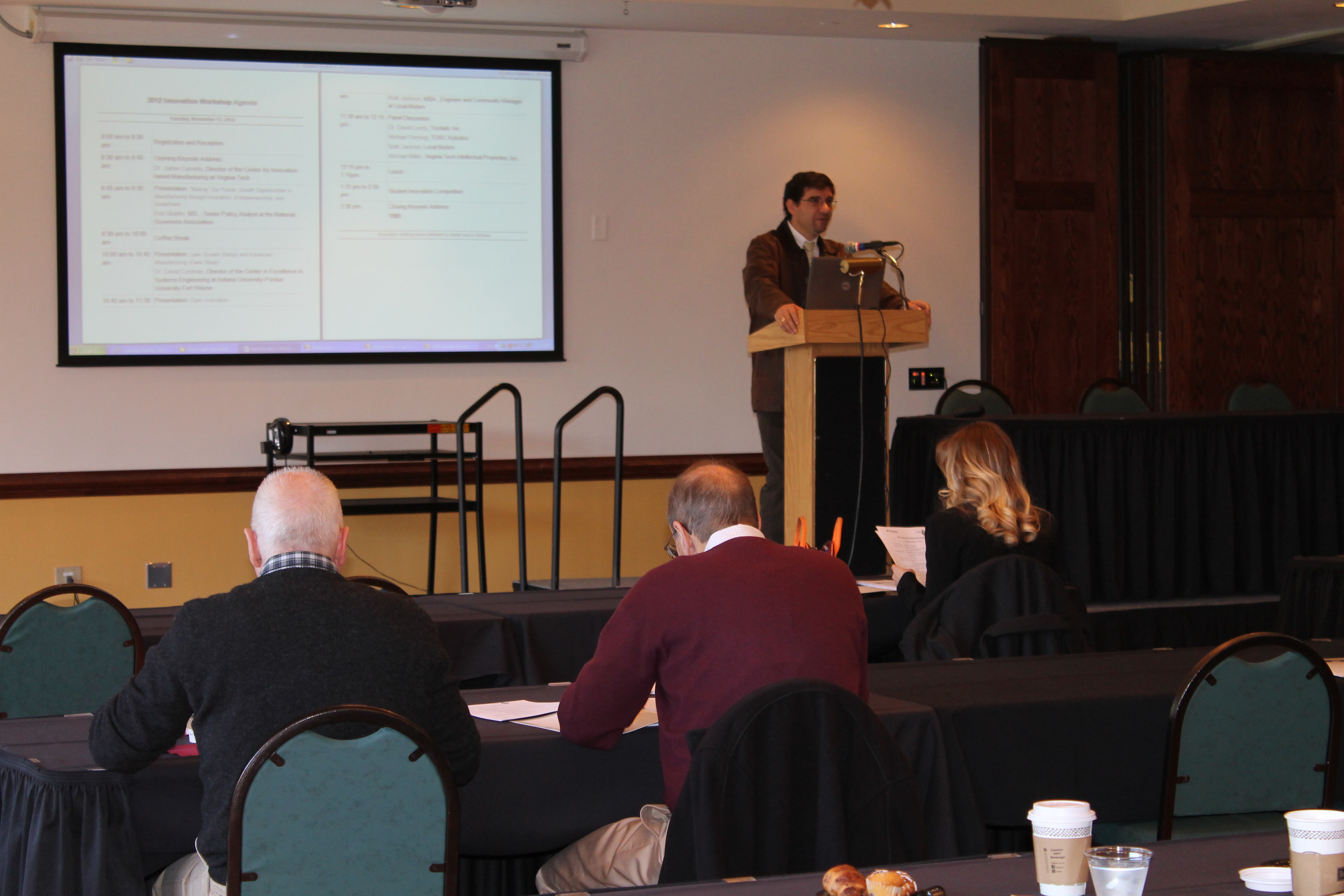
The third innovation-based manufacturing workshop was held on November 13, 2012 at Virginia Tech. Over 40 participants came to the workshop to learn from entreprenours and academics the critical aspects to consider when starting up a business. The workshop held also a student innovation competition where five finalists had the opportunity to present their ideas to a panel. The winner received an award of $5000 in funds to further develop his idea into a commercial product.

Dr. Henry Quesada welcomes participants and speakers.

Continue reading “Third Innovation-based Manufacturing Workshop: A great success!”

RESEARCH BRIEF: Using Concurrent Engineering (CE) in the Furniture Engineering Process

Wang Chao, MS Candidate
wangchao@vt.edu 


Introduction of CE:

Concurrent engineering is an effective methodology used for improving engineering quality and reducing lead time. Sprague, Singh, and Wood (2002) defined concurrent engineering as “a systematic approach to the integrated, concurrent design of products and their related processes, including manufacture and support.” One of the biggest applicants of the concurrent engineering approach is the aerospace industry where different functional teams worked in parallel and the development process results could be rapidly verified from multiple options (Rush and Roy 2000). The most phenomenal result of concurrent engineering compared to the traditional sequential engineering is the reduction of product development lead time, appreciation of total quality (quality of process, quality of organization, and product quality), increased productivity, and decreased costs (costs of rework, scrap, and delays) (Ghodous, Vandorpe, and Biren Prasad 2000).

Synchronize team efforts in the furniture engineering process – CE

CE could also improve the furniture engineering process. Figure 1 shows the difference between concurrent engineering and traditional engineering in a engineering furniture process. In concurrent engineering, the engineering process is paralleled with the mock-up process so that; a great deal of time is saved because engineering could response to any error caused by a design flaw based on daily production feedbacks. Thus by the end of engineering process, the mass production engineering documents are ready by using the same amount of time whereas in sequential engineering, only preproduction documents are completed.

Things are different in the traditional engineering process. The preproduction engineering happens first then the documents will distribute to production to trigger the mock-up process. Production associates will provide feedbacks in the process of making mock-ups. Engineers cannot start the compilation of mass production documents until all the feedbacks are collected from production. Obviously, the traditional engineering takes a lot of engineering iterations, whereas the concurrent engineering requires less engineering design cycles. Also, because feedbacks are given on timely basis, it helps to enhance the design productivity, ensure the product quality, and shorten the lead time.

Continue reading “RESEARCH BRIEF: Using Concurrent Engineering (CE) in the Furniture Engineering Process”

RESEARCH BRIEF: Furniture Engineering Process Analysis

Chao Wang, MS Candidate
Virginia Tech

Andersen and Fagerhaug (2001) defines a process as “a logic series of related transactions that converts input to results or output.” The engineering process is an important component of a business process since it is (Ericsson 1993):

   A chain of logical connected, repetitive activities that

Ÿ   utilizes the enterprise’s resources to

Ÿ   refine an object (physical or mental)

Ÿ   for the purpose of achieving specified and measurable results/products for

Ÿ   internal or external customers

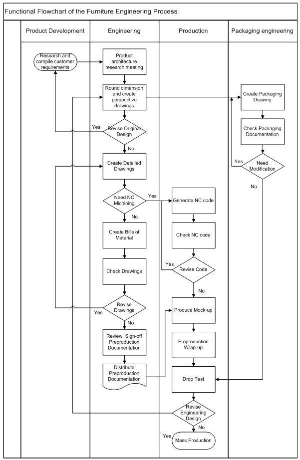
Figure 1. Typical furniture engineering process

Our previous had identified the product family within a case study household furniture manufacturer, next we could further define different processes of engineering for making the family of products. Figure 1 shows a typical furniture engineering process by using functional flow chart.

Further, based on our initial study, we specifically identify 15 major engineering processes for the sofa products. Each process is interpreted in Table 1. 

Table 1. Fifteen engineering major processes

ID Process Interpretation
1 Research Product Architecture Generally, this process is fulfilled by a product architecture discussion meeting. The attendees include associates from three departments which are product development, engineering, and production. The goal of this meeting is to streamline each product architecture in the context of customer requirements, engineering feasibility, and production manufacturability.
2 Create drawings and bills of material (BOM) Drawings include perspective drawings, assembly drawings, part drawings, cutting tool drawings for fabrication. BOM includes both bills of material and bills of hardware.
3 Create fabric cutting drawings The previous step completes the drawings for solid wood and wood-based components. Since most of the upholstery products contain fabric material, the fabric cutting drawing is generated to telling the production associates how to cut the fabric.
4 Apply new material SKU# Since new product inevitably needs to use new material, so engineers need to apply new SKU# for each type of material to facilitate the procurement process
5 Create law tag This is a mandatory tag shows that the product attributes are compliance with the local law for distributing and selling in the destination market
6 Fill out material purchasing form As long as the SKU# is approved, engineer can start to fill out the purchasing form to order certain materials and attach essential drawings and specification to the use of suppliers
7 Create sofa specifications The specifications include both design specification for engineering details and manufacturing specification for fabrication details
8 Create 2.5 axis CNC programs The programs include all the precision machining by the CNC machine such as certain component fabrication templates, part routing programs, and plywood dies for the thermoforming process
9 Check/sign-off/distribute preproduction documents After all the above processes, a preproduction document is established which contains all the essential drawings, bills of material, instruction, specification for fabricating a product or product family. Next, the engineering supervisor will check the document, then the document will sign-off by the engineering manager and distribute to the manufacturing plant.
10 Follow up preproduction mock-up process After releasing the preproduction document, engineers also need to coordinate with production associate on fabricating the mock-up and collect feedback on fabrication difficulties in the mock-up process
11 Compile mass production document According to the fabrication feedback in the mock-up process, engineers could start improving the engineering design and making adjustments in the mass production document
12 Check/sign-off/distribute mass production documents Engineering supervisor and manager do the same process to check, sign-off, and distribute mass production documents
13 Create fabric manufacturing specification This process paralleled with the process of generating production documents. The document not only include detail design specifications, but also contains detailed information on fabric material and what specific area of a certain product will apply this material
14 Create packaging document This process happens after the process of generating production documents. The packaging document include all the drawings, BOM, and specification for packaging a furniture product
15 Create 5-axis CNC program This process parallel with the process of generating production documents. It usually deals with 3D-shaped components that are difficult to generate in the 2.5-axis CNC machine.

The processes in Table 1 that we identified include both primary engineering processes and secondary engineering processes. The primary engineering processes refer to all types of value-added engineering activities performed by the majority of product engineers for designing on-demand product architecture (1-12). The secondary engineering processes refer to the required value-added engineering activities performed by the individual product engineer mainly to facilitate production process (13-15).

Identifying each process is the basis for further analysis on process efficiency. Based on the engineering processes identified above, next the research will focus on identifying essential process metrics such as cycle time and queue time, and finally the value-added time of the process could be identified 

References:

  • Andersen, B., and T. Fagerhaug. 2001. Advantages and disadvantages of using predefined process models. Proceedings fra Strategic Manufacturing, IFIP WG5 7.
  • Ericsson Quality Institute (1993): Business Process Management, Gothenburg, Sweden.